Design Project #2 (Differential-drive robot in artificial gravity)
System
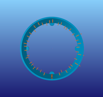
The second project that you will complete this semester is to design, implement, and test a controller that enables a client — who is not an engineer — to steer a differential-drive robot quickly and safely around obstacles as it moves along the inside of a rotating space station under artificial gravity while avoiding hazards, as pictured below:
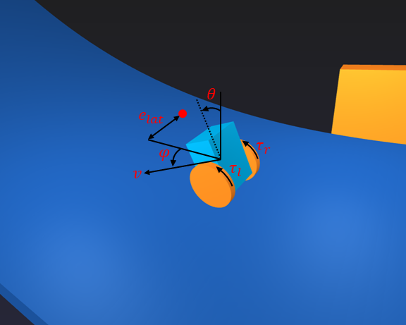
This robot consists of a chassis (dark blue), a left wheel (orange), and a right wheel (also orange). It is called “differential-drive” because two separate motors allow a different torque to be applied to the left wheel and the right wheel:
- If both wheels are rotating forward at the same rate, the robot moves straight.
- If the left wheel is rotating forward faster than the right wheel, the robot turns right.
- If the right wheel is rotating forward faster than the left wheel, the robot turns left.
The client will be given an interface that allows them to specify where on the station ring — farther to the left or farther to the right — they would like the robot to go (this desired position is indicated by a yellow sphere). The job of your controller is to get the robot there while keeping it balanced upright.
Context
A differential-drive transmission is a common design choice for mobile robots. For example, NASA used it in a prototype of Robonaut. You can read more about the reasons why in the textbook Introduction to Autonomous Mobile Robots, Second Edition (Siegward, Nourbakhsh, and Scaramuzza, 2011), also available online (for free from the library at Illinois and at other academic institutions). The two-wheeled, differential-drive design has, of course, also been popularized by Segway.
Artificial gravity is one way to keep a mobile robot anchored to a space station. In particular, if the space station is rotation with angular velocity \(\omega_{station}\) and if the radius of the station — the distance from the center of rotation to its inner surface — is \(r_{\text{station}}\) , then the robot will “feel” as if it were being pulled outward by gravity with acceleration equal to the centripetal accleration
\[g = r_{\text{station}}\omega_{\text{station}}^2\]Artificial gravity is also one way to mitigate the health impacts of microgravity on human astronauts. For example, astronauts lose more than 1% of mineral density in weight-bearing bones for each month they are in zero gravity (see The Human Body in Space for more information).
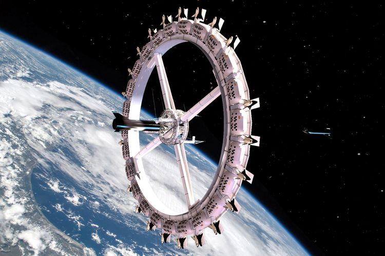
Many assessments of artificial gravity in space missions have been performed by NASA and others, resulting in concepts like Nautilus-X or the Voyager Space Station, a “space hotel” pictured below that may begin construction as early as 2026:
Model
If we assume (incorrectly) that the inside of the space station is flat and not curved upward, then the motion of the system is governed by ordinary differential equations with the following form (see Studies of Systems with Nonholonomic Constraints: the Segway and the Chaplygin Sleigh (Tuttle, 2014) for a derivation):
\[\begin{bmatrix} \dot{e}_{lat} \\ \dot{v} \\ \ddot{\phi} \\ \ddot{\theta} \end{bmatrix} = f(e_{lat}, v, \phi, \dot{\phi}, \theta, \dot{\theta}, \tau_l, \tau_r)\]The details of the function \(f\) get a little complicated:
\[\begin{bmatrix} v \sin{\left( \phi \right)} \\ \frac{-18.4 \tau_l - 18.4 \tau_r - 14.4 \left(\dot{\phi}^2 + \dot{\theta}^2\right) \sin{\left(\theta \right)} + 37.4 \left(0.48 \dot{\phi}^2 \sin{\left(2\theta \right)} - \tau_l - \tau_r + 23.5 \sin{\left(\theta \right)}\right) \cos{\left(\theta \right)}}{89.9 \cos^2{\left(\theta \right)} - 93.5} \\ \frac{-1.06 \dot{\phi} \dot{\theta} \sin{\left(2 \theta \right)} - 2.4 \dot{\phi} v \sin{\left(\theta \right)} - 1.08 \tau_l + 1.08 \tau_r}{0.96 \sin^2{\left(\theta \right)} + 1.03} \\ \frac{-7.49 \dot{\phi}^2 \sin{\left(2 \theta \right)} + 15.6 \tau_l + 15.6 \tau_r + 2.4 \left(3.08 \tau_l + 3.08 \tau_r + 2.4 \left(\dot{\phi}^2 + \dot{\theta}^2\right) \sin{\left(\theta \right)} \cos{\left(\theta \right)} - 367.0 \sin{\left(\theta \right)}\right)}{5.76 \cos^2{\left(\theta \right)} - 5.99} \end{bmatrix}\]So, you are encouraged to use the symbolic description of these equations of motion that is provided with the project code — there is no need to transcribe them yourself.
In these equations:
- \(e_\text{lat}\) is the lateral error (m), or the distance from the center of the robot (more precisely, from the wheel center, or the point halfway between its two wheels) to a line that passes through the red arrow around the station ring — if this quantity is positive, then the robot is too far to the left; if this quantity is negative, then the robot is too far to the right
- \(\phi\) is the heading error or yaw (rad). It is the difference between the orientation of the robot and the direction of the station ring — if this quantity is positive, then the robot is pointing too far to the left; if this quantity is negative, then the robot is pointing too far to the right
- \(\dot{\phi}\) is the turning rate or yawing velocity (rad/s) — positive means the robot is turning left
- \(\theta\) is the pitch angle (rad) — positive means the chassis is pitching forward
- \(\dot{\theta}\) is the pitch rate (rad/s)
- \(\tau_R\) is the right wheel torque (\(N \cdot \text{m}\)) applied by the chassis to the right wheel — positive torque will cause this wheel to rotate forward
- \(\tau_L\) is the left wheel torque (\(N \cdot \text{m}\)) applied by the chassis to the left wheel — positive torque will cause this wheel to rotate forward
Sensors provide measurements of all these variables (although these sensors do not provide any information about the station ring — the extent to which it is curving upward or the location of obstacles, for example). Actuators allow you to choose what torques will be applied, up to a maximum of \(\pm 1\;\text{N}\cdot\text{m}\).
The code provided simulates the motion of this system and also derives the equations of motion in symbolic form (ae353_segbot.ipynb).
The goal is to design a controller that enables a client who is not an engineer to steer the robot as fast as possible around the ring of the space station without causing it to fall off the edge or to hit any obstacles.
Your tasks
In this project, we would like you to be more specific about what you mean by “success” and to provide quantitative evidence supporting the claim that you have (or have not) succeeded. People often think about this in terms of requirements and verifications.
What is a requirement?
A requirement is a property that the system you are designing must have in order to solve your problem (i.e., a thing that needs to get done). A good requirement is quantifiable—it involves a number that must be within a certain range in order to solve your design problem. A good requirement is also both relevant (it must be satisfied—it is not optional) and detailed (it can be read and understood by anyone). Here is an example of a requirement that says what needs to get done but that most engineers would consider unacceptable:
The robot shall move along the ring.
This requirement is not detailed. One way to improve it would be to say what it means to move along the ring:
The wheel center shall remain close to the centerline of the ring.
This requirement is not quantifiable. One way to improve it would be to say how close:
The wheel center shall remain within \(\pm 0.1~\text{meters}\) of the ring centerline.
Most engineers would argue that this requirement still needs improvement. How long must the wheel center remain close to the centerline of the ring? Is there an upper bound on the time it must take for the wheel center to get close to the centerline of the ring, assuming it starts somewhere else? Must this requirement be satisfied only if the station is spinning at its nominal rate, or must it be satisfied for any spin rate within certain bounds? Must this requirement be satisfied no matter what the initial conditions are? Or, are there particular operating conditions within which the requirement applies? How fast must the robot be moving along the ring? Must the robot remain upright and moving at all in order to satisfy this requirement, or can it fall over and remain still so long as its wheel center is near the centerline of the ring when it falls? These are examples of reasonable questions that might be asked by an engineer reviewing the requirement. Your task is to define one requirement—that is quantifiable, relevant, and detailed—that makes clear what the system you are designing must do in order for your goal to be achieved.
Below follows a brief, and incomplete, list of guidlines followed by most engineers while writing requirements:
-
Shall formatting: Requirements shall be in “shall” format. A requirement should use the language: “ITEM A shall TASK A”. This language minimizes ambiguity.
-
Compound requirements: Requirements should not have and conjunctions or transitions in them. For example, try to avoid “and”, “but”, “or”, “further”, “also:, etc. If you use these words, often you are defining two separate requirements.
-
Ambiguous requirements: Requirements shall be simple sentences that minimize ambiguity. You should not include time constraints without stating the point from which timing begins. You should not include maximum limits without defining the equilibrium conditions. You should not use ambiguous language that you do not FIRST (before the requirements and verifications) define.
-
Requirements without initial conditions: It is insufficient to say “The absolute value of MEASURE A shall not exceed CONSTRAINT A.” when you are talking about a measure that changes with time, depends on initial conditions, and varies with user inputs. For example, what if MEASURE A is the pitch of an aircraft and CONSTRAINT A is 5 degrees. The absolute value of the pitch angle shall not exceed 5 degrees. To satisfy this requirement, you must design a system that is not capable of producing pitch angles that exceed 5 degrees. Whereas this may be what an engineer wants, often it is not. Instead, consider the requirement “Given an initial condition of CONDITION A and user input of INPUT A, the absolute value of MEASURE A shall not exceed CONSTRAINT A.”
-
Unverifiable requirements: Requirements must be verifiable. This means that you must be able to prove that they are exactly met or not. For example, the requirement “The MEASURE shall be less than CONSTRAINT A after CONSTRAINT B seconds from initialization for all initial conditions between CONDITION A and CONDITION B.“ is not verifiable in simulation. This is because there are uncountably infinite initial conditions between CONDITION A and CONDITION B. To verify this requirement in simulation, one would have to run infinite simulations. Consider this instead, “The MEASURE shall be less than CONSTRAINT A after CONSTRAINT B seconds from initialization for initial condition CONDITION A.”, “The MEASURE shall be less than CONSTRAINT A after CONSTRAINT B seconds from initialization for initial condition CONDITION B.”,”, “The MEASURE shall be less than CONSTRAINT A after CONSTRAINT B seconds from initialization for initial condition CONDITION C.”,”. This set of requirements is verifiable in simulation because there are only a finite number of initial conditions that must be simulated.
-
Plus and minus: Engineers are often tempted to use the ± symbol in requirements and verifications. Often, this is a mistake. The requirement “MEASURE A shall remain within the limits ± CONTRAINT A” can be ambiguous. Are you defining a connected range or a disconnected range? Language such as “The absolute magnitude of MEASURE A shall not exceed CONSTRAINT A” is less ambiguous. Here it is clear that you are using a connected range.
-
Requirements that constraint design: Requirements should never constrain the design of a system. For example, if a system needs to allow astronauts to enter it and to exit it in space “The system shall include an airlock” is an insufficient requirement. This is because this requirement enforces that the system uses an airlock. Instead, consider “The system shall support egress of humans in space”. “The system shall support ingress of humans in space”. These requirements do not constrain the design of the system at all.
-
Requirements of a requirement: A requirement of a requirement should not be used. For example, you should not say “Our requirements must be sufficient to enforce TASK A.”. Instead, list goals and accompanying requirements. For example, “The goal of the project is to ITEM A. Therefore, the system shall TASK A subject to CONSTRAINTS A”.
What is a verification?
A verification is a test that you will perform to make sure that the system you are designing meets a given requirement. A good verification is based on a measurement—it checks that a quantity is in the range specified by the requirement. A good verification also has a set of instructions for how to make the measurement (an experimental protocol) and for how to interpret the results (methods of data analysis and visualization that provide evidence the requirement has been met). Consider the requirement given above (which, as we have said, still needs improvement):
The wheel center shall remain within \(\pm 0.1~\text{meters}\) of the ring centerline.
Here is a verification of this requirement that most engineers would consider unacceptable:
The system will be tested in simulation.
This verification is not based on a measurement. Here is a better version that is based on a measurement:
The error between the wheel center and the ring centerline will be found in simulation.
This verification does not include a set of instructions for how to make the measurement or for how to interpret the results. Here is a better version that does include a set of instructions:
PyBullet will be be used to simulate the robot. The data generated by this simulation will be imported into a Jupyter Notebook for analysis with Python. The lateral error — the perpendicular distance between the wheel center and the ring centerline — will be found at each time step. The maximum absolute value of lateral error over all time steps will be reported. If this maximum value is less than \(0.1~\text{meters}\), the requirement is met.
Most engineers would argue that this verification still needs improvement. For example, does the simulation generate the same results every time, or is there variation? Just as you saw on your first design project, it seems reasonable to suspect that different initial conditions will produce different results. A reasonable engineer, then, would question whether or not the results of only one simulation would really show that the requirement is met. Many verifications also provide more than just a single number as evidence—for example, they might produce a figure (e.g., a plot of error as a function of time) or some other type of visualization. Your task is to define one verification for your requirement that has a measurement and a set of instructions for how to make the measurement and how to interpret the results.
Below follows a brief, and incomplete, list of guidelines followed by most engineers while writing verifications:
-
Types of verifications: There are four fundamental ways to verify a requirement. This is by inspection, demonstration, test, and analysis. In this order, each verification method increases in rigor.
-
Verification by inspection: Verification by inspection relies on visual, auditory, olfactory, tactile, taste observations from humans. Suppose the requirement is: “The system shall be red”. An example of verification by inspection is as follows: “REQUIREMENT A is verified by inspection. A randomized group of 15 volunteers will be asked to observer the system. They will be asked ‘What color is this system’, and their responses will be recorded. REQUIREMENT A is verified if and only if the majority of the volunteers’ responses include the keyword ‘red’”.
-
Verification by demonstration: Verification by demonstration is the manipulation of the system as intended in use to verify the results satisfy the parent requirements. Suppose the requirement is: “The system shall move box 32-DCA from location 16-B and place it in location 17-B”. An example of verification by demonstration is as follows: “REQUIREMENT A is verified by demonstration. Box 32-DCA is placed in location 16-B. The system is placed 0.5 meters away radially from box 32-DCA on a shared level surface. The system is initiated. REQUIREMENT A is verified if and only if box 32-DCA is in location 17-B upon system termination.”
-
Verification by test (often called verification by simulation): Verification by test is the process by which the system is subjected to a finite number of tests. A test is defined as a predetermined time series of initial conditions, user inputs, system conditions, etc. Suppose the requirement is: “The absolute magnitude of the system’s speed shall not exceed 0.5m/s”. An example of verification by test is as follows: “REQUIREMENT A is verified by test. The system is initialized in CONDITION A. Virtual user inputs are scheduled as INPUTS A. The system is engaged. After 10 seconds, the system is disengaged. The speed of the system is recorded via doppler radar every 0.25 seconds from engage to disengage. The maximum speed recorded by the doppler radar is recorded as MAXIMUM A. The system is initialized in CONDITION B. Virtual user inputs are scheduled as INPUTS B. The system is engaged. After 10 seconds, the system is disengaged. The speed of the system is recorded via doppler radar every 0.25 seconds from engage to disengage. The maximum speed recorded by the doppler radar is recorded as MAXIMUM B. REQUIREMENT A is verified if and only if MAXIMUM A is less than or equal to 0.5m/s and MAXIMUM B is less than or equal to 0.5m/s.”
-
Verification by analysis: Verification by analysis is the process by which a system is analyzed via models and calculations. This varies from verification by test because no specific experiments are conducted. Suppose the requirement is: “The absolute magnitude of the system’s speed shall not exceed 0.5m/s”. An example of verification by analysis is as follows: “REQUIREMENT A is verified by analysis. The equations of motion of the system are derived via Lagrangian mechanics. The time solution of the system’s speed is solved via the method of undetermined coefficients. The maximum of the time solution of the system’s speed as a function of the initial conditions and user inputs is determined via the Karush-Kuhn-Tucker theorem. REQUIREMENT A is verified if and only if the global maximum of the time solution of the system’s speed is less than or equal to 0.5m/s for all admissible initial conditions and user inputs.”
-
Required information in verifications: Just like the “Experimental Methods” section of a journal style paper, verifications should describe the steps that will be performed in enough detail that they could be understood and repeated exactly by a colleague with no exposure to this class or this design project. For example, it is insufficient to say “REQUIREMENT A will be verified via simulation”
-
Negative form of verification: Verifications must not be written in negative form, i.e., “… if MEASURE A exceeds CONSTRAINT B, then the requirement is not verified.”. In general, verifications are written in the positive form, i.e., “… if the MEASURE A is less than the CONSTRAINT B, then the requirement is verified.”
-
Errors regarding data collection in verifications: When a verification uses data collection, there must be no ambiguity surround these data. You must explicitly state which data are collected, when the collection starts, at which frequency the data is collected, which tool is used to generate the data, and exactly how the data is analyzed. It is insufficient to say “REQUIREMENT A is verified by running a simulation and collecting the data that it gives. If the MEASURE A does not exceed CONSTRAINT A, the requirement is verified.” Instead, consider, “REQUIREMENT A is verified by running an instance of the PyBullet simulation provided at SOURCE A subject to INITIAL CONDITION A. MEASURE A, MEASURE B, and MEASURE C are output from the simulation at a frequency of FREQUENCY A. These data are gathered for a duration of LEGNTH A seconds. When LENGTH A seconds have elapsed, these data are analyzed by METHOD A. REQUIREMENT A is verified if, and only if, METHOD A of MEASURE A, MEASURE B, and MEASURE C proves that MEASURE A does not exceed CONSTRAINT A.”
-
Ambiguous data description in verification: Engineers must avoid ambiguity when discussing data analysis. This is especially true with respect to verifications. If data is generated that are used to verify a requirement, the analysis proving the verification of the requirement must be understood by all peers, even those with no exposure to the project. For example, it is insufficient to say, “REQUIREMENT A is verified with the MEASURE A has VALUE A at the final time step.” What does final time step mean? What are time steps? Instead, consider “A rollout is defined as a simulation with initial conditions of CONDITIONS A and a duration of DURATION A. REQUIREMENT A is verified if and only if MEASURE A has VALUE A at DURATION A of a rollout.”
-
Visual verification of graphs: Visual verification of graphs is an insufficient method of verification. If numerical data is generated, numerical data must be used in verification.
Ambiguous language in requirements and verifications
Many words and phrases are ambiguous and either require strict definitions or should not be used. They can have more than one meaning depending on the reader and background. Be sure that all language in requirements and verifications is not ambiguous at all. Imagine you have no background knowledge in either this project or engineering. Your requirements and verifications should still be easily understandable. Below follows a brief, and incomplete, list of ambiguous words and phrases avoided by most engineers while writing requirements and verifications:
- converge
- final
- end
- means
- good
- complete
- sufficient
- varying
- error
- fulfilled
- original
- upper
- lower
- within
- be able to
- be capable of
What requirement and verification would be most relevant?
Remember that your goal is to enable a non-expert to steer the robot safely around the station while avoiding obstacles. Think about requirements and verifications in terms of your client’s needs. What must be satisfied by your control system to enable safe steering?
Things you need to do
Please do the following things:
- Define a requirement and a verification.
- Linearize the equations of motion.
- Show that the linearized system is controllable.
- Design a stable controller.
- Implement this controller and test it in simulation.
- Follow the instructions you wrote to verify that your requirement is (or is not) satisfied.
Note: The tasks outlined above should be completed with the “bumpy” setting set to False, which is the default setting. This ensures that environments are generated without obstacles.
If you’ve finished these tasks and are looking for an extra challenge, you can earn a small bonus by setting “bumpy” to True and completing the following additional tasks:
Test the ability of at least one real person to steer the robot — with your controller — safely around the station ring. It would be best if this person were a real “non-expert” — someone not in your group, not in this class, and maybe outside the college of engineering!
There are many other ways to go beyond minimum requirements (how does the spin rate impact the performance of your controller? how fast is it possible to get the robot to move around the ring without it falling off, falling down, or hitting anything? how does performance vary with the choice of speed at which the robot tries to move?) — come talk to us if you want an extra challenge.
As always, remember that your controller is not expected to “work” in all cases and that you should try hard to establish limits of performance (i.e., to break your controller). At minimum, you should rigorously vary the initial conditions, as you did in your first design project.
Your deliverables
We will use Canvas for submitting design projects. You must create a compressed folder (.zip) titled DP2-submission with the code and the report in the format described below and submit by October 20, 23:59:59:
Code:
This code will satisfy the following requirements:
- It must be in a folder called code (lower case).
- It must include a single notebook called GenerateResults.ipynb that could be used to reproduce all of the results that you show in the report.
- It must include all the other files (with the right folder structure) that are necessary for GenerateResults.ipynb to function.
- It must not rely on any dependencies other than those associated with the conda environment.
Report:
- It must be a single PDF document that conforms to the guidelines for Preparation of Papers for AIAA Technical Conferences. In particular, you must use either the Word or LaTeX manuscript template.
- It must have a descriptive title that begins with “DP2” (e.g., “DP2: Control of a differential-drive robot in artificial gravity”).
- It must have the author name and affiliations.
- It must tell a story that shows you have found and explored something that interests you.
- You may organize your report however you like, but it should at the minimum have these sections:
- Abstract. Summarize your entire report in one short paragraph.
- Nomenclature. List all symbols used in your report, with units.
- Introduction. Prepare the reader to understand the rest of your report and how it fits within a broader context.
- Theory. Derive a model and do control design.
- Experimental methods. Describe the experiments you performed in simulation in enough detail that they could be understood and repeated by a colleague. At minimum, this section should clearly define your requirement and verification.
- Results and discussion. Show the results of your experiments in simulation (e.g., with plots and tables) and discuss the extent to which they validate your control design - in particular, the extent to which they verify your requirement. As always, remember to focus on establishing limits of performance.
- Conclusion. Summarize key conclusions and identify ways that others could improve or build upon your work.
- Acknowledgements. Thank anyone outside your group with whom you discussed this project and clearly describe what you are thanking them for.
- References. Cite any sources, including the work of your colleagues.
- It should preferably be about 5 pages in length — it will be hard to show off your work with anything shorter, and it will be hard to keep readers’ attention with anything longer.
Submission Instructions
To make it easier logistically, there will be two assigned submissions for this project on Canvas. Please submit the following separately:
- Report: Submit a pdf version of your report
- Code: Compress your code into a zip file and submit the zip file.
Evaluation
Your work will be evaluated based on completion of the tasks and the resulting description of the results, on submission of working code, and your report being formatted correctly. Late submission will be penalized (by up to 25% for the first week of delay—prorated for the actual amount of delay—and 50% after then), but extraordinary efforts may receive extra commendation.
Frequently asked questions
How do I get started?
The first thing you should do is update your local copy of the repository with the DesignProblem02 file, to do this, please follow the installation instructions, very specifically, follow the ‘Do this every time’ section and run the command
git pull
This will update your local copy of the repository with the code for Design Problem 02. Verify that you can run the simulation, and mess around a little bit with different actuator commands (e.g., constant wheel torques) to get a sense for how the system responds.
After that, if you have read the entire project description and are not sure how to proceed, then take your best guess and ask a question on Canvas. Improving your ability to get unstuck by asking a good question is an explicit goal of this course.